Classify Air Compressors. Explain construction and working of centrifugal pump with sketch.
According to method of compression
A. Reciprocating compressor
- This type of compressor compresses air by reciprocating action of piston inside a cylinder.
- It is suitable for producing high pressure.
B. Rotary Compressor
- In a rotary compressor, air or gas is compressed due to the rotation of impeller or blades inside a casing similar to a rotary pump.
C. Centrifugal compressor
- A machine in which compression of air to desired pressure is carried out by a rotating impeller as well as centrifugal action of air.
According to method of delivery pressure
A. Low pressure - up to 1.1 bar
B. Medium pressure - 1.1. to 8 bar
C. High pressure – 8 to 10 bar
D. Very high pressure - above 10 bar
According to principle of operation
A. Positive displacement
- In this type, pressure of air is increased by reducing the volume by positive displacement of air with piston or with rotating element.
- These are capable with low volume flow rate. Examples: Reciprocating compressor, Roots Blower etc.
B. Roto dynamic OR steady flow compressor
- In this type, compression of air is carried out by a rotating element imparting velocity to the flowing air and developed desired pressure. Here compression is achieved by dynamic action of rotor.
- Examples: Centrifugal, Axial flow, etc.
According to the number of stages
A. Single stage compressor - pressure up to 5 bar
B. Multistage compressor - pressure above 5 bar
According to method of the number of cylinder
A. Single cylinder
B. Multi cylinder
According to method of the pressure limit
A. Fans - pressure ratio 1 to 1.1
B. Blowers - pressure ratio 1.1 to 2.5
C. Compressor - pressure ratio above 2.5
According to volume of air delivered
A. Low capacity - volume flow rate up to 9 m3/min
B. Medium capacity - volume flow rate 10 m3/min to 300 m3/min
C. High capacity: Volume flow rate above 300 m3/min
According to fluid to be compressed
A. Air compressor
B. Gas compressor
C. Vapour compressor
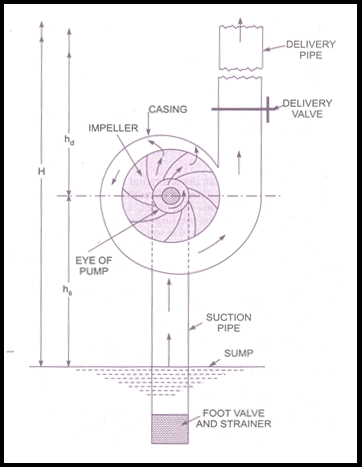
Construction:
Main components: 1. Impeller 2. Casing 3. Suction pipe 4. Delivery pipe
Function of main parts in detail as below:
Impeller
- It is rotor which is provided with a series of backward curves vanes or blades.
- It is mounted on a shaft which is coupled to an external source of energy (electric motor), which imparts required energy to the impeller.
- It gets mechanical energy and converts it to kinetic and pressure energy of the fluid.
- Liquid enters the impeller through an eye of the impeller, high energy liquid than enters the pump casing.
Casing
- It is an air tight passage surrounding the impeller, designed in such a way that kinetic energy of the water discharged at the outlet of the impeller is converted into pressure energy before the water leaves the casing and enters the delivery pipe.
- Material of the casing is generally cast iron or cast steel.
- The efficiency of the pump depends on the type of casing used. (Volute casing, Vortex casing and casing with guide blades
Working
- “A centrifugal pump works on a principle that when the liquid is rotated by an external prime mover, it is thrown away from the axis of rotation and a centrifugal head is imparted which makes it possible to raise to the higher elevation.”
- Before starting a centrifugal pump, liquid is filled in the suction pipe, impeller, casing and a delivery pipe up to a delivery valve. This is known as priming. During priming delivery valve is kept close.
- After priming, prime mover (electric motor) is started; delivery valve is still kept closed.
- Energy given to the impeller by external source (i.e. prime mover) is transferred to working fluid which increases the kinetic energy and pressure energy of the fluid.
- The rotation of the impeller causes strong suction at the eye of the pump.
- After the impeller attains its normal speed, the delivery valve is opened and liquid is allowed to flow through the impeller vanes and it attains higher velocity at the outer periphery.
- Liquid enters into casing, due to special design of casing the velocity of liquid decreases and pressure energy hence increases.
- With high pressure energy and negligible kinetic energy liquid enters into delivery pipe and is lifted to the required height.
- At that instant partial vacuum is created at the eye of pump due to centrifugal action of impeller on liquid.
- This helps liquid to rush through the suction pipe towards the impeller eye, to take place of liquid which has left the impeller vanes.
- When the pump is to be stopped the delivery valve should be first closed to stop the back flow of liquid.